
Power System Analysis and Design (MindTap Course List)
6th Edition
ISBN: 9781305632134
Author: J. Duncan Glover, Thomas Overbye, Mulukutla S. Sarma
Publisher: Cengage Learning
expand_more
expand_more
format_list_bulleted
Related questions
Question

Transcribed Image Text:File Preview n 1: The Optimized Receiver (25 Points)
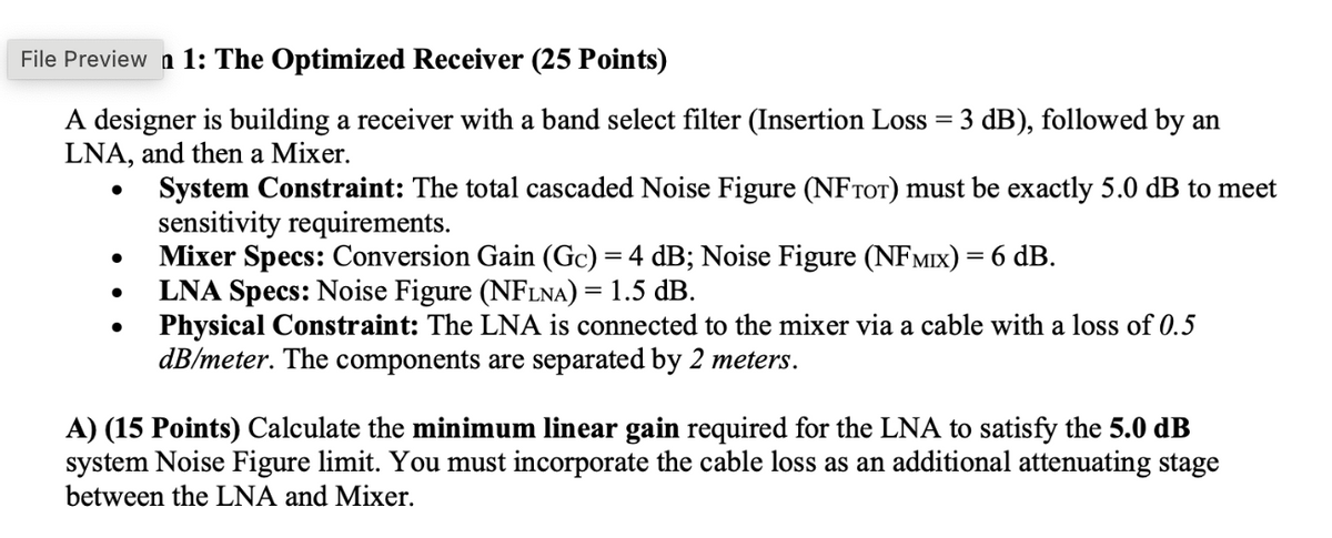
A designer is building a receiver with a band select filter (Insertion Loss = 3 dB), followed by an
LNA, and then a Mixer.
•
•
•
•
System Constraint: The total cascaded Noise Figure (NFTOT) must be exactly 5.0 dB to meet
sensitivity requirements.
Mixer Specs: Conversion Gain (Gc) = 4 dB; Noise Figure (NFMIX) = 6 dB.
LNA Specs: Noise Figure (NFLNA) = 1.5 dB.
Physical Constraint: The LNA is connected to the mixer via a cable with a loss of 0.5
dB/meter. The components are separated by 2 meters.
A) (15 Points) Calculate the minimum linear gain required for the LNA to satisfy the 5.0 dB
system Noise Figure limit. You must incorporate the cable loss as an additional attenuating stage
between the LNA and Mixer.

Transcribed Image Text:B) (10 Points) The system uses low-side injection with an IF of 100 MHz and an LO of 900 MHz. If
the desired RF signal is received at -55 dBm and the Mixer provides an Image Rejection Ratio (IRR)
of 25 dB, what is the maximum allowable power (in dBm) of an image signal at the RF input if the
image and desired signal must be equal in power at the IF output?
Expert Solution
This question has been solved!
Explore an expertly crafted, step-by-step solution for a thorough understanding of key concepts.

Step by stepSolved in 2 steps with 2 images

Knowledge Booster

Recommended textbooks for you
- Power System Analysis and Design (MindTap Course ...Electrical EngineeringISBN:9781305632134Author:J. Duncan Glover, Thomas Overbye, Mulukutla S. SarmaPublisher:Cengage Learning

 Electricity for Refrigeration, Heating, and Air C...Mechanical EngineeringISBN:9781337399128Author:Russell E. SmithPublisher:Cengage Learning
  Delmar's Standard Textbook Of ElectricityElectrical EngineeringISBN:9781337900348Author:Stephen L. HermanPublisher:Cengage Learning
 EBK ELECTRICAL WIRING RESIDENTIALElectrical EngineeringISBN:9781337516549Author:SimmonsPublisher:CENGAGE LEARNING - CONSIGNMENT
Power System Analysis and Design (MindTap Course ...
Electrical Engineering
ISBN:9781305632134
Author:J. Duncan Glover, Thomas Overbye, Mulukutla S. Sarma
Publisher:Cengage Learning
Electricity for Refrigeration, Heating, and Air C...
Mechanical Engineering
ISBN:9781337399128
Author:Russell E. Smith
Publisher:Cengage Learning
Delmar's Standard Textbook Of Electricity
Electrical Engineering
ISBN:9781337900348
Author:Stephen L. Herman
Publisher:Cengage Learning
EBK ELECTRICAL WIRING RESIDENTIAL
Electrical Engineering
ISBN:9781337516549
Author:Simmons
Publisher:CENGAGE LEARNING - CONSIGNMENT