
Videos
To plot:
The
Answer to Problem 1P
The graph for
The graph for
The amplitude of sine and cosine function is
Explanation of Solution
Given:
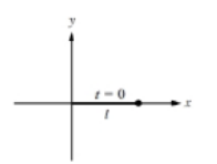
The tip of a one-link robot is initially located at
Time taken for the robot to move form
A one-link robot is length of
Concept used:
Write the expression for the linear frequency.
Here,
Write the expression for the angular frequency.
Here,
Write the expression for the time period.
Write the expression for
Here,
Write the expression for
Here,
Write the expression for the time shift.
Here,
Calculation:
The one-link robot completes one revolution in
Substitute
Substitute
Therefore, the period of the tip of a one-link robot is
Substitute
Therefore, the frequency is
Since the one-link robot initially start form
Substitute
Here,
Substitute
The plot for the
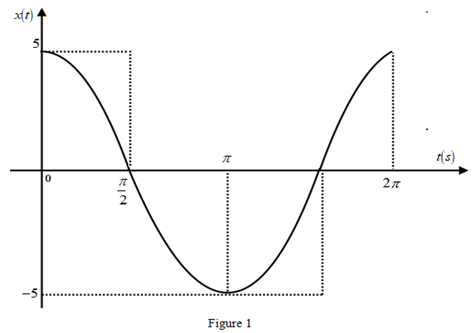
Substitute
Substitute
The plot for the
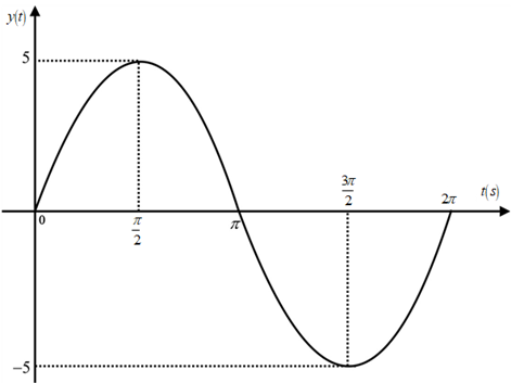
Figure 2
Substitute
Therefore, the time shift of the one-link robot is
The amplitude of sine and cosine function is
Conclusion:
Thus, the graph for
Want to see more full solutions like this?
Chapter 6 Solutions
Introductory Mathematics for Engineering Applications
Additional Math Textbook Solutions
Elementary Statistics: Picturing the World (7th Edition)
Calculus: Early Transcendentals (2nd Edition)
Elementary Statistics (13th Edition)
Introductory Statistics
Elementary Statistics
Thinking Mathematically (6th Edition)


- A mass of 2 slug stretches a spring 1foot. The mass is released from rest from a point 3 feet below the equilibrium position. the medium exerts a damping force numerically equal to 12 times the ins tantaneous velocity. Beginning at t=0 , the system is driven by external force f(t)= 10e-t sin(3t) g=32 ft/s^2 a)Derive the initial value x(t) measure positive downward from the equibrium b) solve the equation of motion c) determine the limit as t approach infinity for f(t)arrow_forwardA mass of 2 slug stretches a spring 1foot. The mass is released from rest from a point 3 feet below the equilibrium position. the medium exerts a damping force numerically equal to 12 times the ins tantaneous velocity. Beginning at t=0 , the system is driven by external force f(t)= 10e-t sin(3t) g=32 ft/s^2 a)Derive the initial value x(t) measure positive downward from the equibrium b) solve the equation of motion c) determine the limit as t approach infinity for x(t)arrow_forwardDetermine the function is linearly independent using wronskian f1(x)= e^2x , f2(x) = xe^2x, f3(x)= x^2e^2xarrow_forward
- Probl Given: eam Shear 12"x12" col, fc=5000 psi. fy=60,000 psi b=14in, h=26in, (3) #8 top and bot #3 stirrups at 8" o.c., wu = 5.0 k/ft L=30ft TOP BARS Wu L Determine: The following values. BOT. BARS STIRRUPS Vu QVC= QVS = Ok? QVn = Smax =arrow_forwardShoring Prodi Analysis Footing Given: Column Footing Po=75 k, PL = 60, qa = 3000 psf, fc=4000 psi, 16" concrete col #5 bars in bottom. h = 12", b = 7'-0" Determine: Analyze Footing Check 2-way shear only 9s= 40 ok? Qu= d = V₁ = QVC= ok? column width 38arrow_forward2-36 plus slab 20 1.8 16 lumn Analysis, with Moment Pg 0.08 Kn INTERACTION DIAGRAM R4-60.8 " -4 ksi -60 ksi 7-08 12 1.0 08 0.07 0.06 0.05 0.04 0.03 0.02 doo 0.01 с 06 04 b). 00035 e) 11-0 0.25 02 F 4,00050 0.05 010 0.15 0.20 0.25 0.30 PC REAS b) If pg 1% and considering point b, is the column adequate? c) If pg 1% and considering point c, is the column adequate? d) If pg=2% and considering point d, is the column adequate? e) pg=2% and considering point d, is the column adequate? 0.50 yh 075 1.0 035 040 045 PILOT &arrow_forward
- For the Flat Slab or One-way slab and joist (approximate 2'-6" spacing) concrete system, layout the system for a 120ft (36m) x 150ft (45m) building. DO NOT USE THE SAME SYSTEM THAT YOU STUDIED. Cleary show and label the columns and dimension the bays. Make sure you are using the correct bay proportions. Sketch at least one bay in detail. Sketch a section through the system, either overall or a detail, whichever is appropriate. State the effective span range of the system. State the typical depth to span ratio that is used to find the preliminary height h of the system. Using your layout and plan show how you would determine the height h for the elements within the system given a certain bay size. Label your framing plan or section with the depths of the structural elements. Clearly show which direction(s) the elements are spanning.arrow_forwardProb 3a) Column Analysis, no Moment Given: fc=4,000 psi fy=60,000 psi (8) #8 vert. bars, #3@16" Pu= 750 k Determine: a) Is the columns adequate for the load? 18in 18in #3 TIES (8) VERT p = Vert bars QPn Col. Adequate?arrow_forwardProste Given: lysis Concrete beam, 5000 psi, normal-weight concrete Mu(-)-280 k-ft, h=26in, b=16in (4) #8 top and bot #3 stirrups Determine: Check if beam is adequate TOP BARS BOT. BARS As a Pmax Ptc Pmin OM=MR= Adequate? b STIRRUPSarrow_forward
 Algebra & Trigonometry with Analytic GeometryAlgebraISBN:9781133382119Author:SwokowskiPublisher:Cengage